Overview
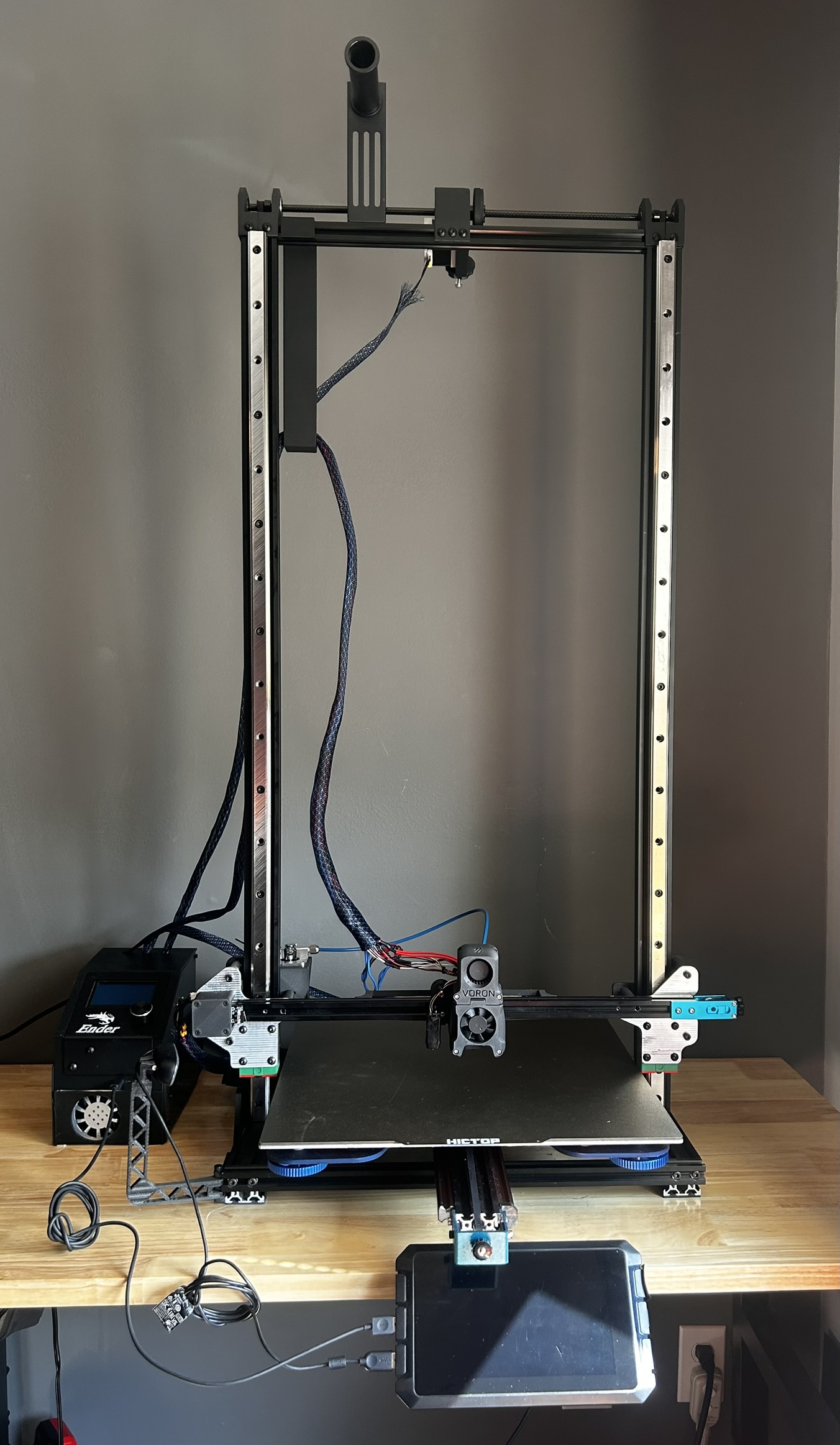
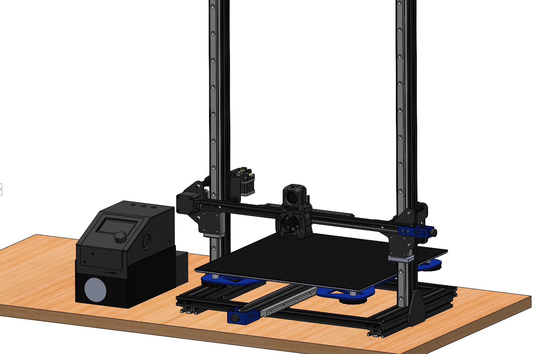
I designed and manufactured a custom dual-extrusion 3D printer that utilizes a servo-actuated secondary nozzle to enable multi-material printing. The development of the printer required multiple design iterations and extensive testing to validate mechanical performance, thermal behavior, and reliability. This project allowed me to apply SolidWorks for both CAD modeling and finite element analysis while also further developing my skills in DC electronics and klipper.
Version 4:
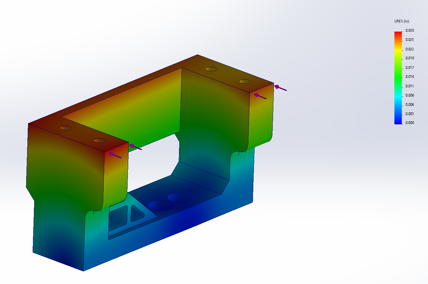
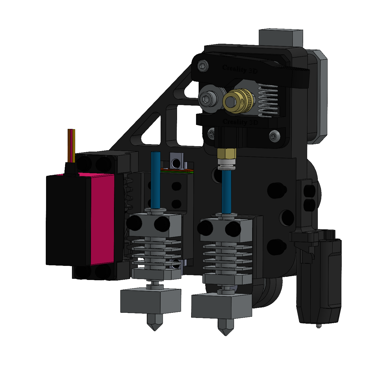
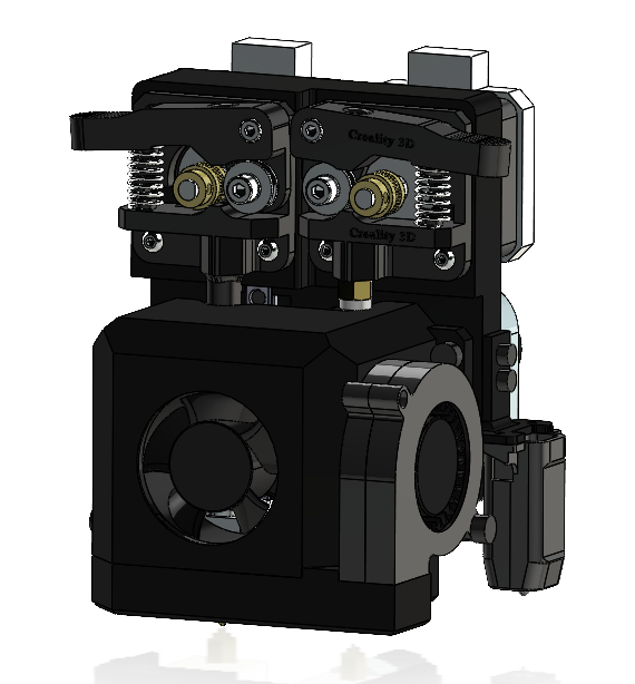
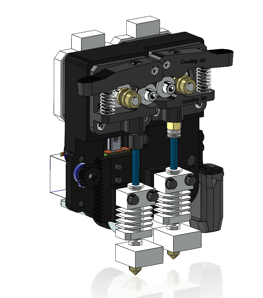
Version 4 represented the first successful implementation of a dual-extrusion system. It retained the same electronics architecture and enclosure as Version 3 but introduced a completely redesigned toolhead. The new design incorporated a high-torque 20 kg servo paired with a lower-pitch rack-and-pinion mechanism to actuate the secondary nozzle. The increased mechanical advantage prevented nozzle slippage during active extrusion. To validate the stiffness of the servo mounting, displacement analysis was performed on the servo bracket to estimate deflection under load and ensure positional accuracy.
The secondary extrusion system was also converted from a direct-drive configuration to a Bowden setup. In the direct-drive arrangement, retracting the inactive nozzle placed the filament in axial compression with no compliant path to relieve the load, causing resistance against the servo motion. The Bowden configuration allowed the filament guide tube to deflect during nozzle retraction, eliminating excessive compressive forces.
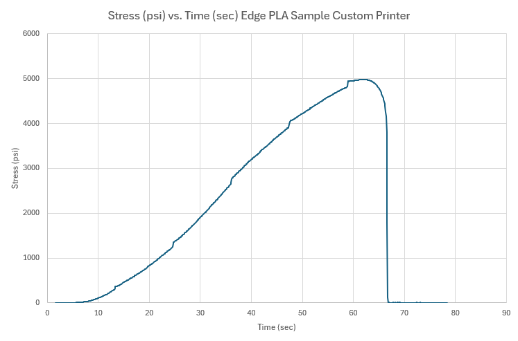
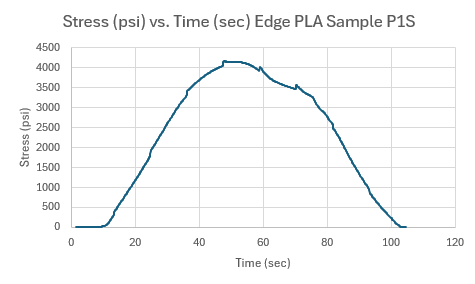
Inital Testing of New Design Concept Before Implementation:
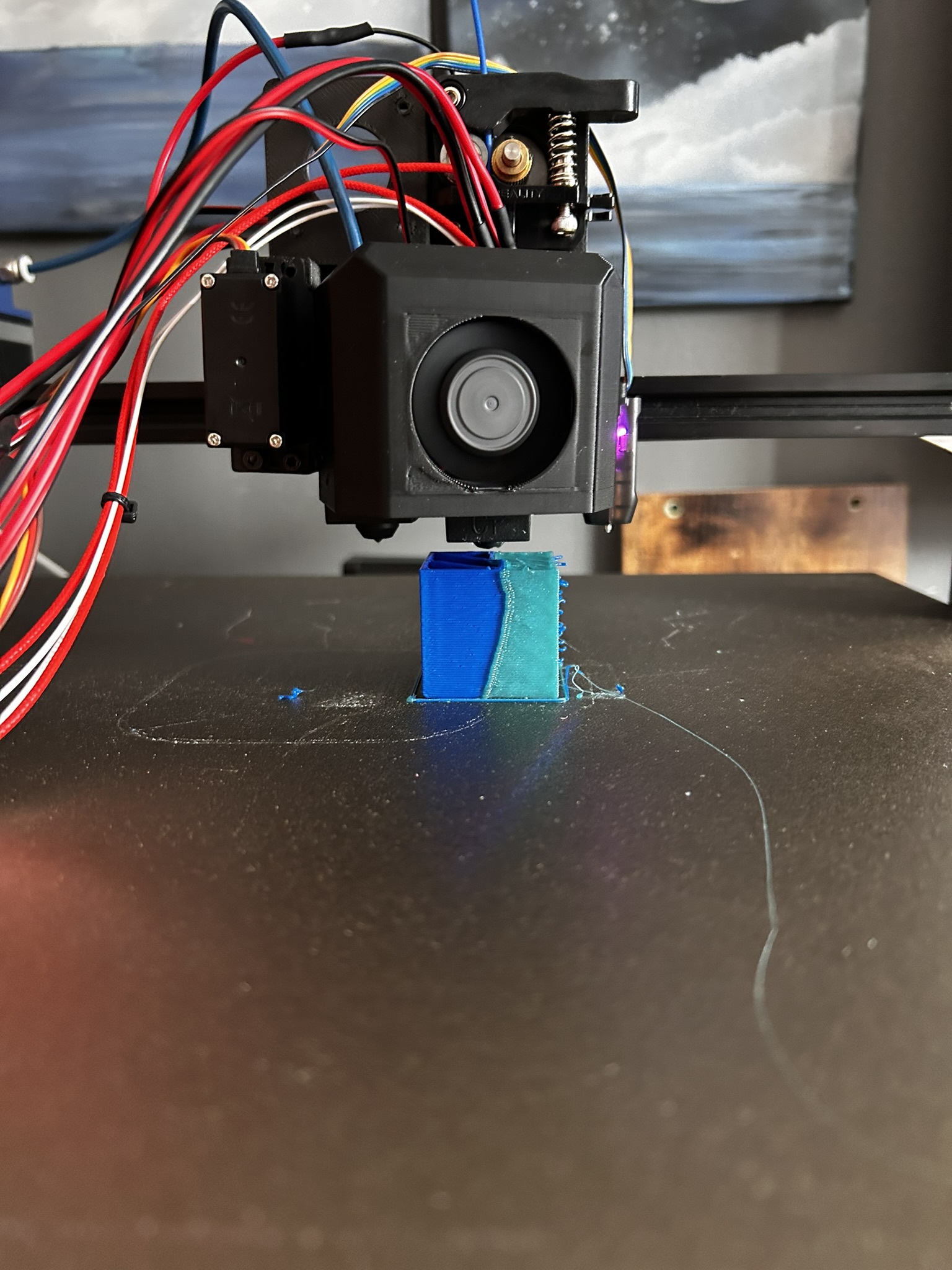
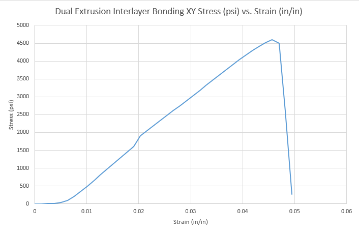
Because version 4 was able to successfuly print with multimaterial, tensile testing was conducted with a sample made of two different PLA’s with the gage length of sample being half one pla and toher other half the other pla. The tensile testing showed a very good potential for strong bonding with the sample breaking at 4500 psi at the intersection of the two materials.
Version 3:
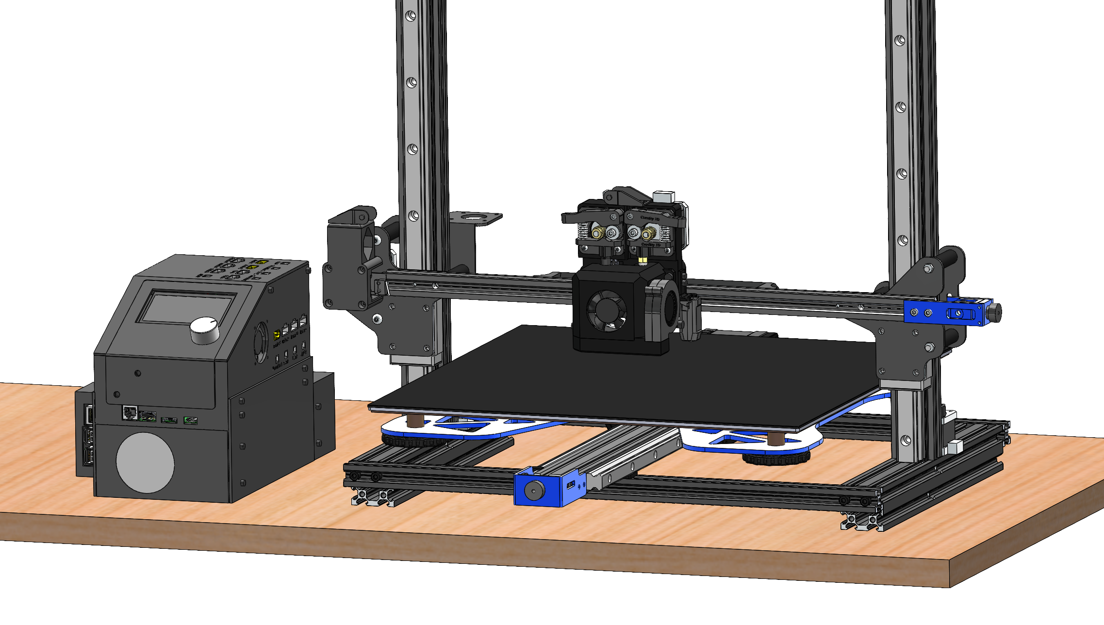
Version 3 marked the first attempt at integration of a dual-extrusion system into the printer. To support the additional hardware required for multi-material printing, a BigTreeTech Octopus control board, paired with a BigTreeTech Pi, was used for network connectivity and remote control. The Octopus board provided the additional stepper drivers needed to feed multiple filaments as well as multiple PWM outputs to drive servos. The entire electronics system was redesigned around a modular enclosure, utilizing XT60 power connectors and JST signal connectors, which allows sensors and actuators to be quickly swapped in the event of a failure. This rebuild required extensive soldering, continuity checks, and voltage verification to ensure safe and reliable operation of the control electronics.
A custom Klipper configuration was developed to manage multiple nozzles, including offsets and macro-based nozzle switching. These macros were integrated into the slicer software so that nozzle changes were automatically inserted into the generated G-code at the appropriate points during a print.
The printer toolhead was also fully redesigned to incorporate a servo-actuated secondary nozzle mounted on a linear rail for smooth motion. A custom homing sequence was implemented to ensure the servo and secondary nozzle returned to a consistent reference position every time the power was turned on, thereby maintaining accurate nozzle alignment during tool changes. While Version 3 successfully demonstrated dual-extrusion capability, it revealed limitations related to high servo current draw and insufficient torque. The force from extrusion overpowered the servo motor and caused the secondary nozzle to slip and lose position. Because of these drawbacks, version 3 was unable to produce a successful 3D print.
Version 2:
Version 2 of the printer focused on improving motion reliability, electronics packaging, and consistency of the heated bed. The original V-wheels, which allowed motion in the system, were replaced with brackets mounted directly to linear rails, resulting in smoother motion, reduced wear, and improved positional accuracy.
I designed and machined custom aluminum brackets to connect the Z-axis linear rails to the X-axis assembly, as polymer components lacked the stiffness required to prevent excessive deflection under the weight of the Z-axis and its motion.
An aluminum platen support was also designed and fabricated to provide full support across the heated bed, addressing sagging that occurred with the original small support.
The electronics enclosure was completely redesigned, and the power supply was upgraded to enhance reliability and prevent overcurrent scenarios.
Tensile testing was performed on printed samples and compared against parts produced on a Bambu Lab P1S to benchmark mechanical performance.
While Version 2 significantly improved reliability over Version 1, it was limited by low print speed and the inability to run custom firmware.
Tensile Testing Data:
Version 1:
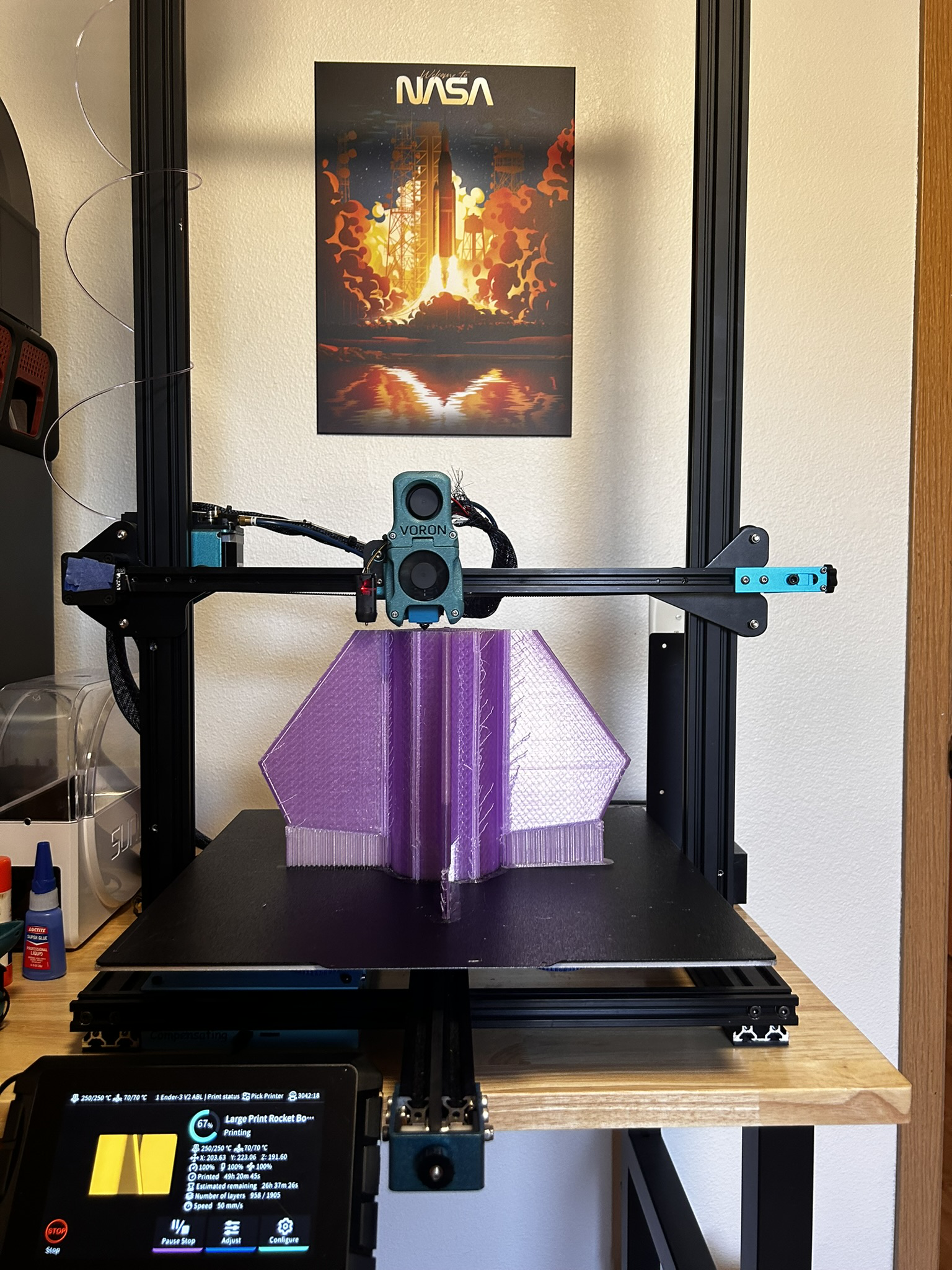
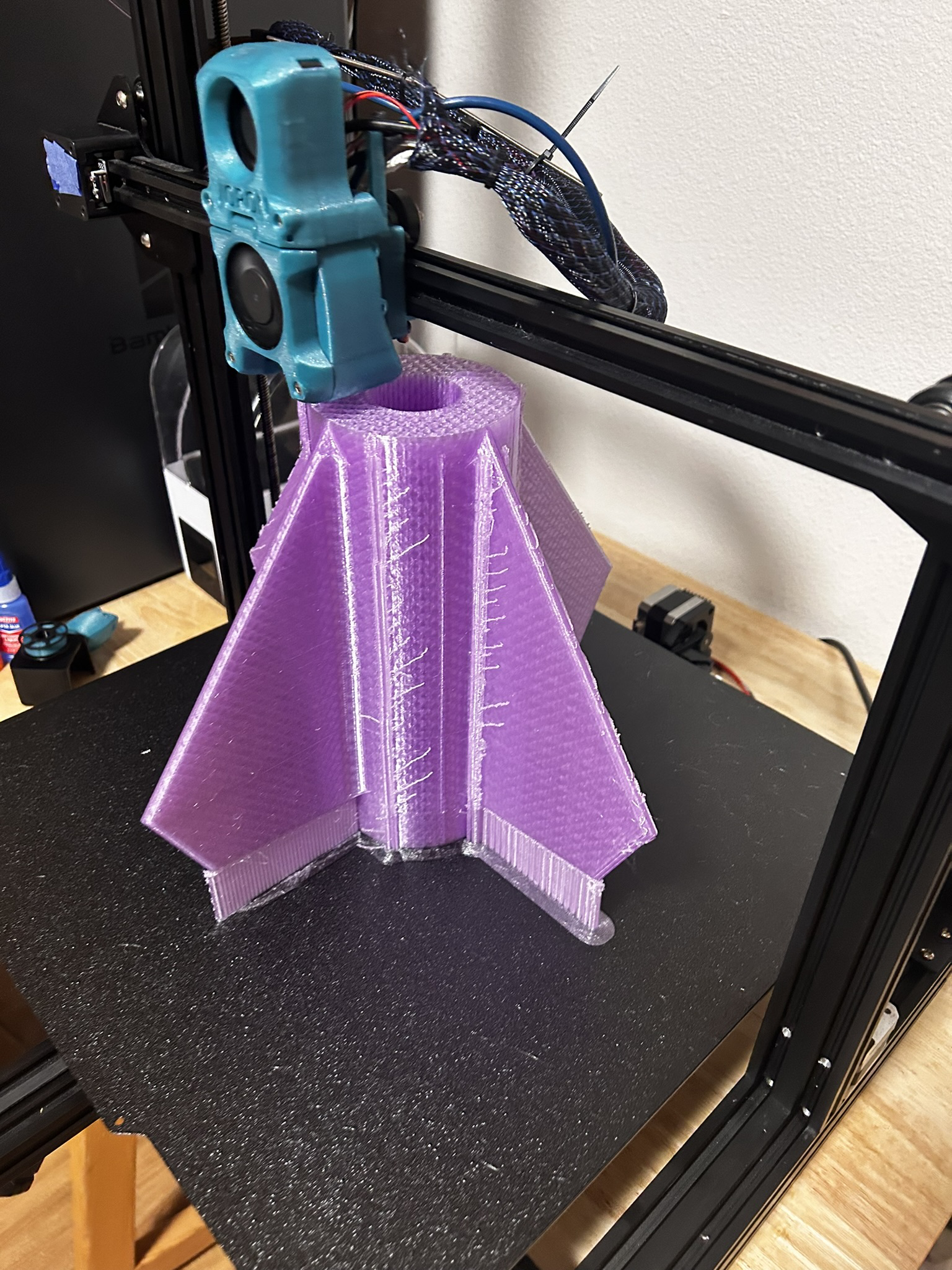
Version 1 of the printer focused exclusively on increasing build volume and used only standard electronics for a basic FDM 3D printer. It was built around an Ender 3 V2 control board running pre-compiled Marlin firmware.
While this version was capable of producing large parts such as rocket components and manufacturing fixtures, it lacked the reliability and consistent performance required for more advanced, long-term use. Version 1: Printing a Rocket