Project Summary
I designed and built a custom mechanical load frame capable of outputting 1200 lbf with 6 inches of travel to measure the tensile, compressive, and bending strength of a wide range of parts and assemblies.
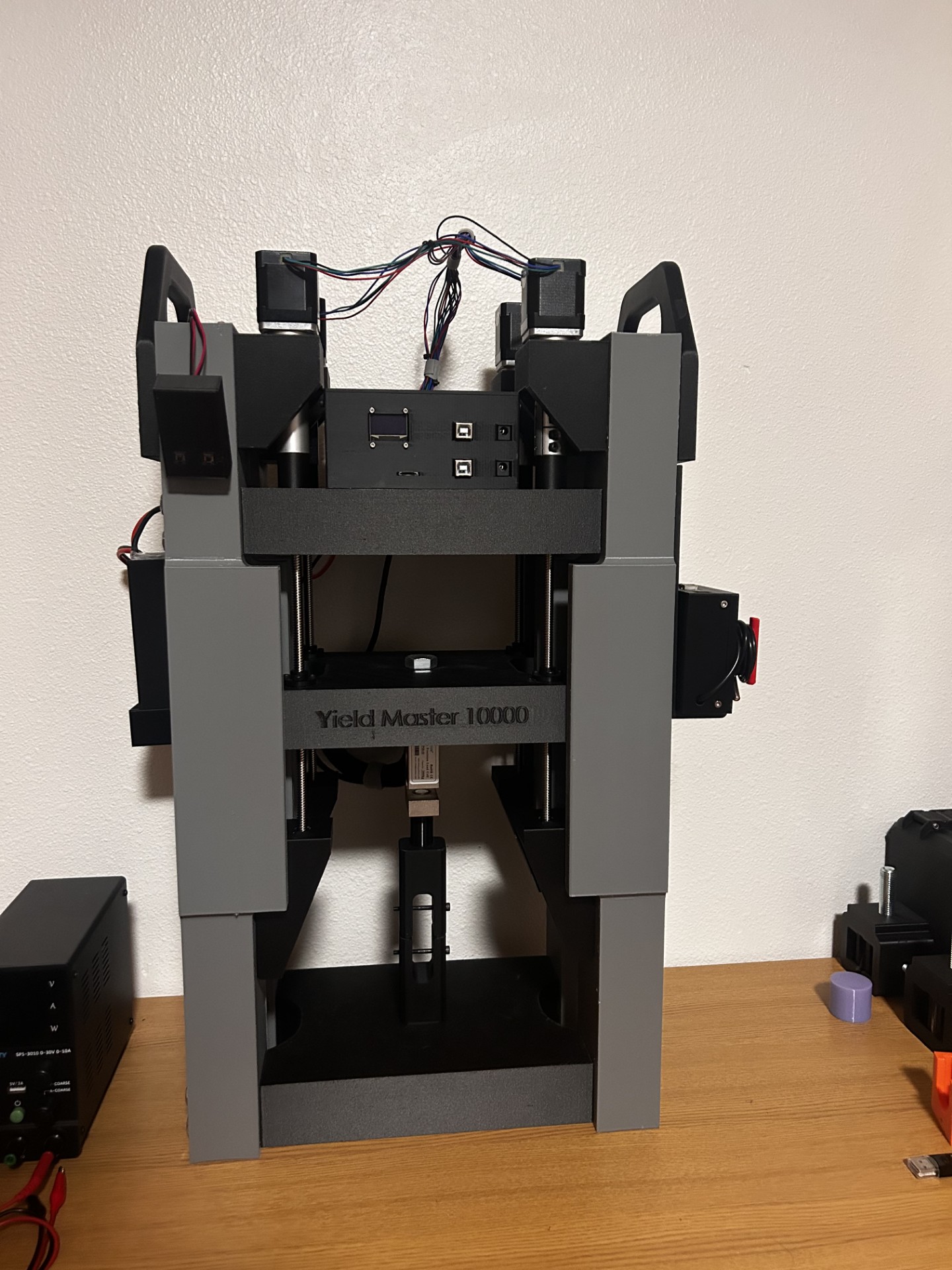
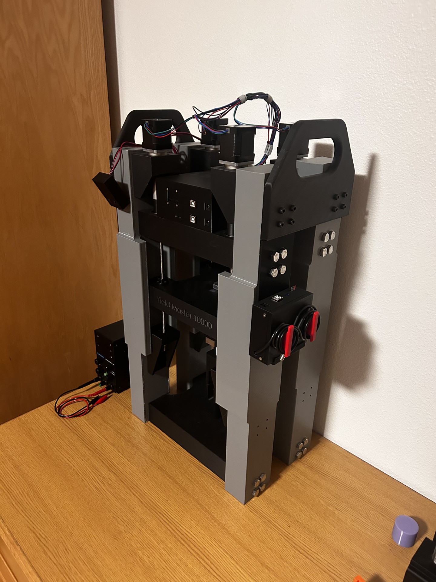
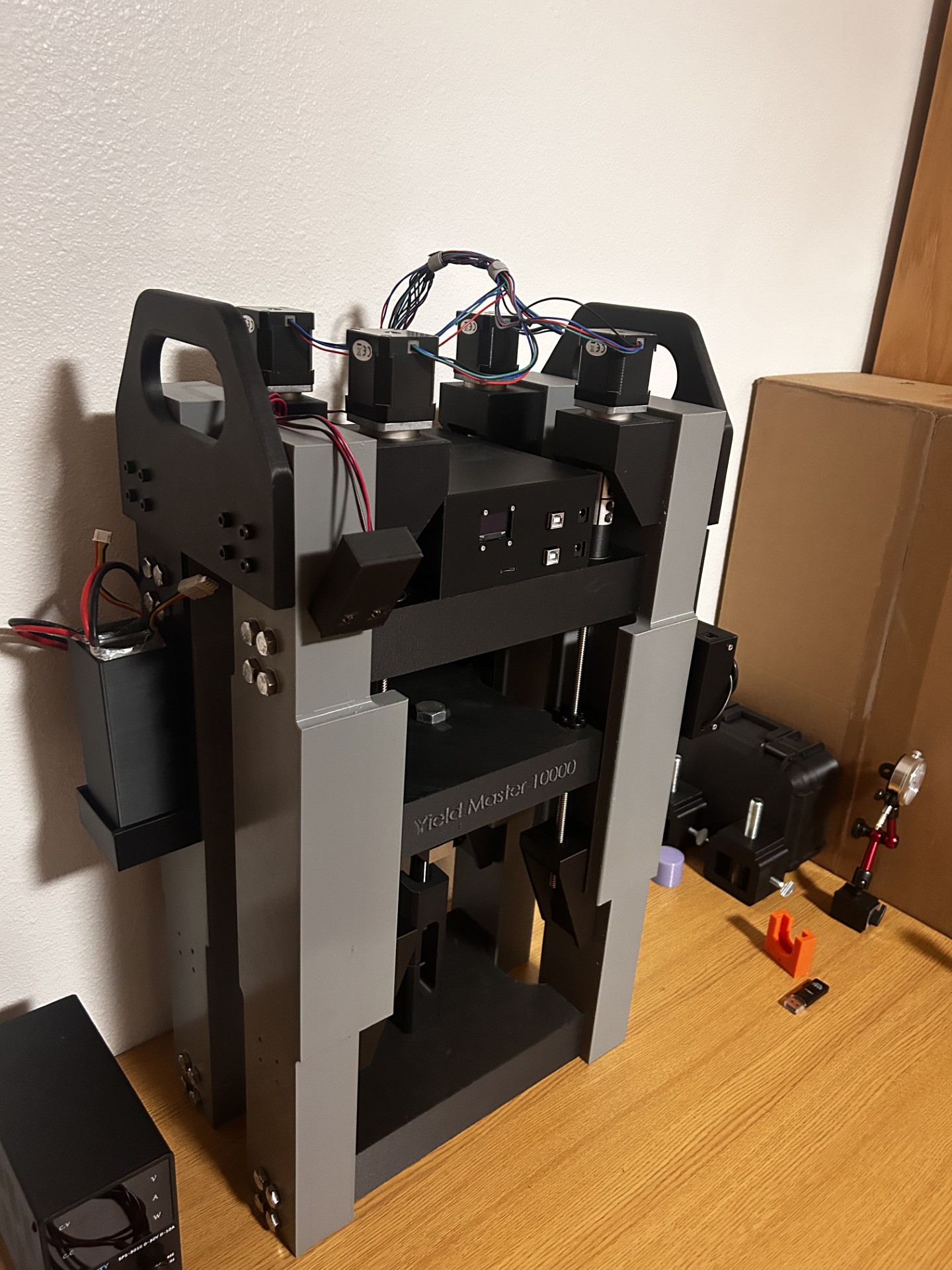
Mechanical Load Frame
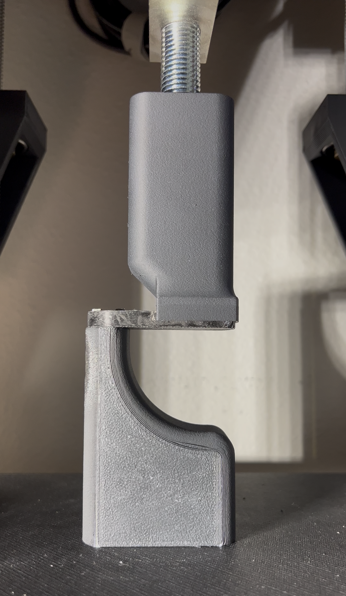
The load frame was designed in SolidWorks and can perform tensile, compressive, and bending tests on a wide range of parts and assemblies. Interchangeable jaws and fixtures are mounted using a single M16 bolt head, allowing test hardware to be quickly swapped to accommodate different specimen geometries.
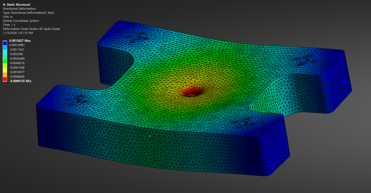
The test platens were fabricated from carbon-fiber-reinforced Nylon-12 to maximize stiffness. The carbon fiber within the polymer significantly increases the elastic modulus of the polymer, reducing bending and elastic deformation under load. Platen thickness was optimized to limit deflection under the design load of 1200 lbf, with an allowable deflection target of 0.0125 inches. Finite element analysis was performed in ANSYS Mechanical, predicting a maximum deflection of 0.0099 inches at 1200 lbf
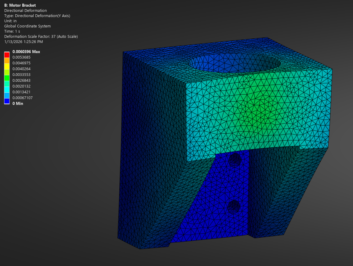
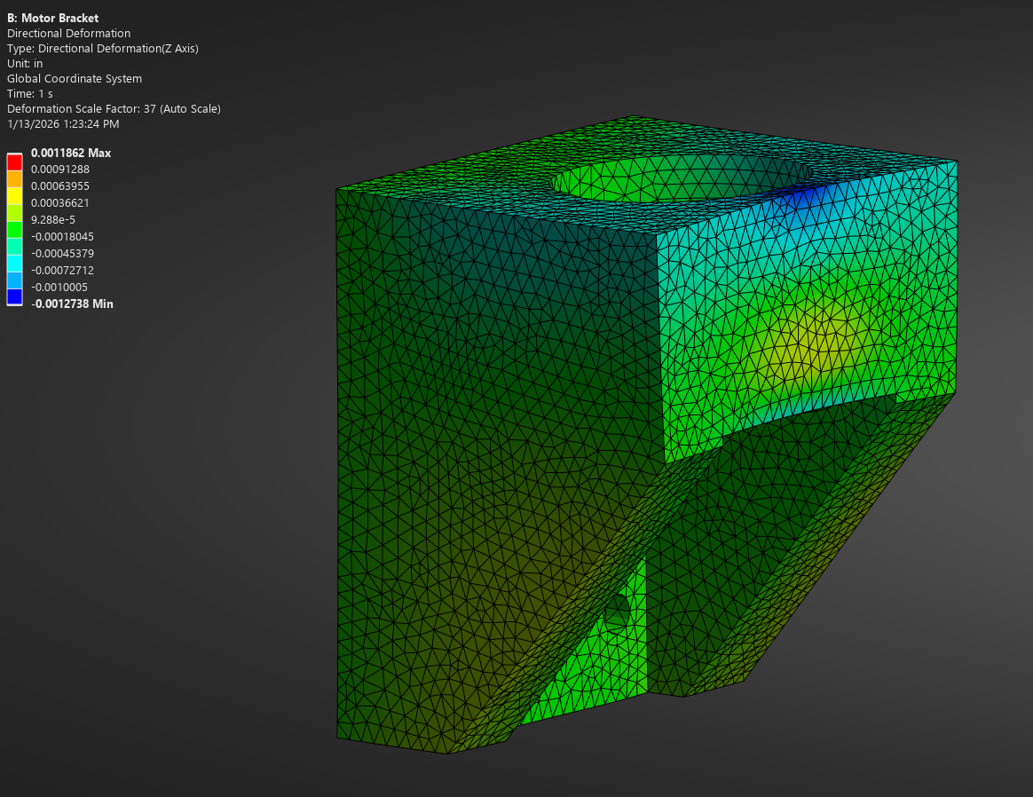
Deflection of the motor mounting brackets were also analyzed, as excessive deformation could lead to mechanical binding and restricted motion in the drive system. Maximum allowable deflections were set to 0.005 inches perpendicular to the applied load and 0.01 in parallel to the load direction. Finite element analysis showed a maximum deflection of 0.001 in perpendicular to the load and 0.006 inches parallel to the load.
Because the platens and motor brackets were produced using FDM additive manufacturing, the predicted deflections from finite element analysis will not match the true deflection due to anisotropy in the printed material. However, finite element analysis estimates served as an estimate. The material properties for the analysis were taken from the Nylon-12CF datasheet for the specific filament used, and the strength and elastic modulus were assumed to be from the weakest print orientation.

Hardware
The system integrates stepper motor drivers, Arduino Unos, OLED screens, load cells, amplifier boards, and SD card modules to enable real-time display and accurate data logging for post-test analysis. The stepper motors are specked to produce 3 Nm of torque and are powered at 24 volts. The motors use TMC2209 drivers with the current limiter set to 1.55A.
A 4400 lbf load cell serves as the primary force measurement device. While specimens should be tested at 20–80% of a load cell’s maximum capacity for optimal accuracy, validation confirmed that the load reading is linear across the full range (0–4400 lbf). The load cell is paired with an amplifier board running at 80 Hz for fast data collection.
An LVDT was initially considered to measure sample deformation directly between the platens. However, this introduced error because the measured displacement included both sample and system deformation, and excessive sensor noise further reduced reliability. Instead, platen separation is measured by utilizing a pair of digital calipers that are connected to the DAQ. This method introduces similar errors, as system deflection is included in the measurement. However, there is very little to no noise when utilizing the digital calipers.
Software
The system is controlled using three Arduino Unos, which communicate via I2C with the stepper drivers, OLED screens, load cell amplifier boards, SD card modules, and digital calipers. Two push buttons on the controller allow the platens to be moved up or down at a fixed speed of 2 inches per minute. In future iterations, additional testing modes will be integrated into these buttons to enable easier operation at variable speeds.
Testing
The Mechanical Load Frame has been very useful in quantifying strengths of different parts and assemblies. For example, I have been able to utilize the load frame to test the strength of forged carbon fiber airbrake pads. I was able to make custom jaws to apply loads and moments of the pad exactly how they would be applied in flight conditions.
Airbrake Pad Fixturing and Test Data
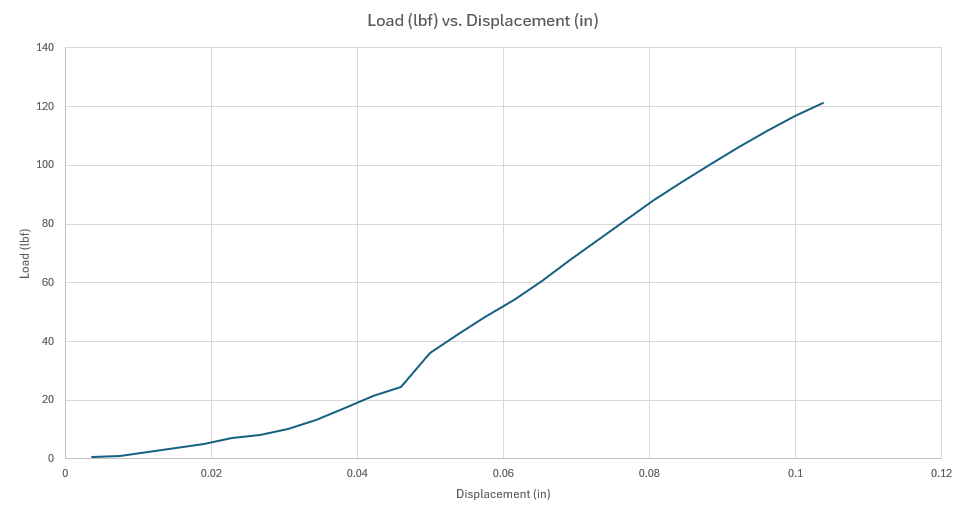
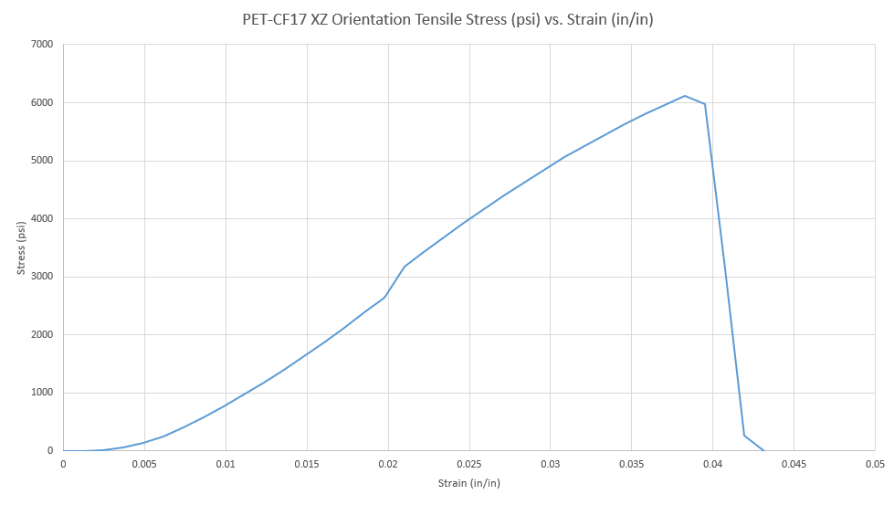
The load frame has also been used to generate mechanical property data for additively manufactured materials. For example, a PET-CF17 blend that I use was characterized through mechanical testing, allowing for realistic strength and stiffness values to be applied during part design.
PET-CF17 Tensile Data XZ Orientation